AA Battery Solar Charger
For higher power solar systems, see the CirKits solar charge controller circuit board kits.
AA Battery Solar Charger
(C) G. Forrest Cook 1999Introduction
This almost trivial circuit may be used to charge a pair of AA or AAA sized rechargeable battery cells from sunlight. The circuit has been used to keep a Palm Pilot and walkman radio running perpetually. This is an unregulated charger, proper charging is achieved by placing the unit in the sun for a known amount of time, this time varies according to the battery type.Specifications
Open Circuit Voltage: about 4.0V
Closed Circuit Current: about 25ma (depending on the solar cell types)
Charge Current:	< 25ma (depending on the solar cell types)
Charge Time AA cells: approximately 1 full day of direct sunlight
Charge Time AAA cells: approximately 1/2 full day of sunlight
Theory
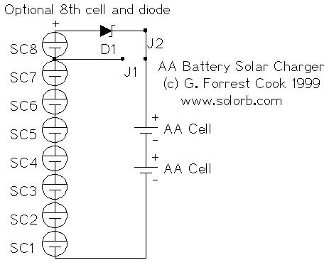
Each of the solar cells develops about 0.5 volts across itself when in full sunlight. The string of 8 solar cells puts out around 4V with no load. When the solar cells are connected to a battery, a current will flow and the battery will charge.Two versions of the circuit are shown in the schematic, the 8 solar cell panel with a diode is the recommended circuit. The diode prevents the battery from discharging through the cells at night and the 8th cell boosts the voltage up enough to compensate for the voltage drop across the diode. For an 8 solar cell panel, connect jumper J2 and disconnect J1. For a 7 solar cell panel, connect jumper J1 and eliminate SC8 and D1. Typically, the jumpers are not necessary, they are shown in the schematic to illustrate two ways to to build the circuit.
For operation in cloudy weather, it may be useful to add one or two additional solar cells. It is a good idea to temporarily insert an amp (microamp) meter in series with the battery to measure the charging current in various light conditions.
Since solar cells are current-limited devices, it is possible to use the circuit as-is to charge a single battery cell. If one cell is all you ever need to charge, five solar cells and a series diode will be sufficient for the task.
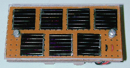
Construction
Lay out the solar cells to determine the size of the circuit board, allow for about 1/4" (1cm) of extra space around all four sides. Cut out one piece of perforated circuit board, one piece of solid PC board, and one piece of 1/8" clear plexiglass in this dimension. File all 3 pieces to achieve smooth edges.Drill 2 holes down the center line of the 3 pieces while holding them together allowing room for the screws to pass between the solar cells. Mount the two battery holders on the blank piece of circuit board with screws or silicon rubber glue. If the solar cells don't have wire connections, solder thin wires to the cells. Wire-wrap wire works well for this. Be careful not to overheat the solar cells, use a small soldering iron and only touch the cells for a few seconds at a time. The solar cells should be secured to the perf board with a drop of silicon rubber on the back side, or they can be held in place with the wires of the solar cell if you have the right kind of cell. Wire all of the cells in series, plus to minus, connect the two end wires to longer wires that go to the diode and battery holder. Typically, the positive connection is the metal on the back of the solar cell and the negative connection is the wire grid on the blue (front) side.
Using a pair of 3/4 inch 6-32 machine screws and nuts or washers, make a sandwich of the 3 boards. Use the nuts or washers to make gaps between the board layers, it is important to prevent any contact between the solar cells and the plexiglass. The solar cells are very brittle and will break under compression.
If you want to make the panel waterproof, cut 4 thin strips of solid circuit board or other plastic to fit around the sides of the sandwich. Glue these boards to the sides of the assembly with silicon rubber. Apply a small drop of glue to where the screws go through the plexiglass.
Alignment
None required unless you count pointing the panel at the sun.Use
Insert two rechargeable cells in the battery holders, point the device at the sun, and let batteries charge for a few hours. Larger cells will need more charging time. The solar array should be placed in direct sun, it should not be shaded in any way. It might be a good idea to monitor the battery voltage during the first few charge cycles to get an idea of how much time is needed to reach a full charge.Do not let the rechargeable cells overheat. If the charger is left outdoors in the summer, the excess heat can cause the cells to leak out their electrolyte goo, ruining the cells. Operating the charger indoors behind a window may help to reduce the heat. Operation behind a window will also cause a drop in the charge current, resulting in a longer charge time.
This circuit works with rechargeable alkaline cells, NICD cells, or any other rechargeable that has a potential of 1.5V or lower per cell. If you build the 7 cell version (no diode), remove the cells at night to prevent discharge through the solar cells.
It is advisable to connect a volt meter across the battery with a pair of alligator clips to observe the battery voltage as it charges. If you have a lot of batteries to charge, it is best to charge cells that are matched by brand. If possible, use cell pairs that start with a similar voltage, this allows both cells to finish charging at the same time.
The NiCd Memory Effect
Keep in mind that the so-called NiCd "memory effect" is largely an urban legend that started from a legitimate early 1960s Nasa experiment involving first generation NiCd cells charged and discharged within a very tight voltage range. The two biggest killers of modern NiCd cells are overheating during charging, and reverse voltages applied to the weak cells as the result of the complete discharge of multi-cell NiCd packs. The NiCd cells in cheaper appliances such as cordless phones and portable vacuum cleaners will last a lot longer if they aren't left on the charger 24 hours a day.Overheating can cause the loss of electrolyte, resulting in lowered cell capacity. Reverse voltage can cause conductive dendrites to grow in the cells making them self-discharge more rapidly. So called "memory effect" dischargers can actually cause the reverse voltage problem if used on multiple cell packs. The weakest cell in a pack will go to zero volts, then negative volts as the stronger cells discharge. Discharging can be a good way to insure that all cells are charged from the same starting point, just be sure to limit the minimum discharge voltage to around 1V per cell. The BatteryUniversity.com has a good article on the behavior of aging NiCD cells, and tips on cell restoration.
Parts
SC1-SC8 single photovoltaic solar cell, .5V, 20 to 50 ma output each in full sunA company called Electronix Express sells a solar cell array (part #08SLC07) that contains 10 cells and a built-in diode, the array will work nicely for this project and costs around $7.
D1 1x 1N5818 Schottky Diode
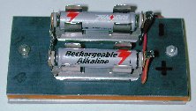
Battery Holder 1x 2 cell AA or AAA battery holder
Battery 2x AA or AAA NiCD or NiMH rechargeable cells
Perf Board 1x for mounting solar cells
PC board 1x solid piece for mounting battery holder
Plexiglass 1x approx. 1/8" thick, cut to size
misc hardware, wire
Samsung mobile tips, tricks, secrets
Other secret tricks for samsung mobile or cellphone If you have downloaded corrupted or incompatible Java midlets or other media,
which are causing problems with the phone, try this
*2767*JAVA# Java Reset and (Deletes all Java Midlets)
*2767*MEDIA# Reset Media (Deletes All Sounds and Pics)
*2767*WAP# Wap Reset
*2767*CUST# Reset Custom EEPR0M
*2767*FULL# Reset Full EEPR0M (Caution)
For example : *2767*JAVA# would be keyed in as *2767*5282#
Note : Not all codes will work with SGH-C100.
The master reset code is:
#*7728#
This will not delete anything from your
mobile phone, but set each and eveything to its
default/standard setting as it was on the time of purchase.
To unlock your phone put a sim from another company,
now type *#9998*3323# it will reset your phone. Push exit and then push 7,
it will reset again. Put your other sim in and it will say sim lock,
type in 00000000 then it should be unlocked. Type in *0141# then
the green call batton and it's unlocked to all networks.
This code may not work on the older phones and some of the newer phones.
If it doesn't work you will have to reset your phone without a sim in it
by typing *#2767*2878# or *#9998*3855# (not tested)
Other Samsung Codes
*#9998*4357# Help Menu
*#9998*5282# Java menu (GRPS/CSD settings for JAVA server)
*#9999#0# Monitor Mode
*#9999# or *#9998*9999# Software Version
*#8888# or *#9998*8888# Hardware Version
*#9998*746# or *#9998*0746# or *#0746# Sim Infos
*#9998*523# or *#9998*0523# or *#0523# Display Contrast
*#9998*842# or *#9998*0842# or *#0842# Vibration On (until you push OK)
*#9998*289# or *#9998*0289# or *#0289# Buzzer On (until you push OK)
*#9998*288# or *#9998*0288# or *#0288# Battery & Field Infos
*#9998*377# or *#9998*0377# Error log
*#9998*778# or *#9998*0778# or *#0778# Sim Service table
*#9998*782# show date and alarm clock
*#8999*638# show network information
*#9998*5646# change operator logo at startup
*#9998*76# production number
*#9998*968# view melody for alarm
*#9998*585# Non-Volatile Memory (NVM)
*#3243948# Digital Audio Interference Off
*#32436837# Digital Audio Interference On
Simple 5V power supply for digital circuits


Summary of circuit features
- Brief description of operation: Gives out well regulated +5V output, output current capability of 100 mA
- Circuit protection: Built-in overheating protection shuts down output when regulator IC gets too hot
- Circuit complexity: Very simple and easy to build
- Circuit performance: Very stable +5V output voltage, reliable operation
- Availability of components: Easy to get, uses only very common basic components
- Design testing: Based on datasheet example circuit, I have used this circuit succesfully as part of many electronics projects
- Applications: Part of electronics devices, small laboratory power supply
- Power supply voltage: Unreglated DC 8-18V power supply
- Power supply current: Needed output current + 5 mA
- Component costs: Few dollars for the electronics component + the input transformer cost
Circuit description
This circuit is a small +5V power supply, which is useful when experimenting with digital electronics. Small inexpensive wall tranformers with variable output voltage are available from any electronics shop and supermarket. Those transformers are easily available, but usually their voltage regulation is very poor, which makes then not very usable for digital circuit experimenter unless a better regulation can be achieved in some way. The following circuit is the answer to the problem.
This circuit can give +5V output at about 150 mA current, but it can be increased to 1 A when good cooling is added to 7805 regulator chip. The circuit has over overload and therminal protection.
The capacitors must have enough high voltage rating to safely handle the input voltage feed to circuit. The circuit is very easy to build for example into a piece of veroboard.
Pinout of the 7805 regulator IC.
- 1. Unregulated voltage in
- 2. Ground
- 3. Regulated voltage out
Component list
7805 regulator IC
100 uF electrolytic capacitor, at least 25V voltage rating
10 uF electrolytic capacitor, at least 6V voltage rating
100 nF ceramic or polyester capacitor
Modification ideas
More output current
If you need more than 150 mA of output current, you can update the output current up to 1A doing the following modifications:
- Change the transformer from where you take the power to the circuit to a model which can give as much current as you need from output
- Put a heatsink to the 7805 regulator (so big that it does not overheat because of the extra losses in the regulator)
Other output voltages
If you need other voltages than +5V, you can modify the circuit by replacing the 7805 chips with another regulator with different output voltage from regulator 78xx chip family. The last numbers in the the chip code tells the output voltage. Remember that the input voltage muts be at least 3V greater than regulator output voltage ot otherwise the regulator does not work well.
IR remote control computer interfacing


With some little modification the transmitter part of this circuit can be used with computer. The idea is to cut the wire going to 7555 IC pin 4. Connect the wire end coming form receiver to computer input and the end going to 7555 chip pin 4 to one computer output (computer inputs and outputs should be TTL level signals).
This circuit is a good example how to do the computer to IR remote interfacing in both ways. All you need is a simple program for sampling the data coming form receiver (few kHz sample rate is enough). When you want to control something, then just send the sampled data to the transmitter part of this circuit.
The circuit can be easily connected to PC parallel port for your experiments. If you are experimenting only with reception, then one good idea might be to connect the receiving part of the circuit to joystick port, because there are easy to use input lines and also poer for the whole circuit.
You can probably use the little receiver modules made by Sharp, and marketed by Radio Shack (among other places), in a sort of wired-OR arrangment. Sony TV sets do this internally... the IR receiver is in a wired-OR arrangement with the chip which decodes the front-panel pushbuttons, and the "guts" of the TV simply listen to this signalling bus for their commands. On my KV-20XBR, at least, the control board of the TV literally cannot tell whether a button-press was on the front panel or on the IR remote... it's all bits on a Control-S/SIRCS bus by then!
>2)An amplification stage to drive the output IR led.General recommendations:
>
>3)The output IR led.
[1] Use one of the IR receiver/demodulator modules (or several, in parallel) to receive and clean up the signal, and use this signal to switch a 40 kHz oscillator on and off. Do _not_ try to receive, amplify, and retransmit the modulated carrier directly... you will probably find that you circuit is extremely noise-sensitive and difficult to "trim". The receiver modules have a tuned 40 kHz amplifier circuit built in, which eliminates _lots_ of noise.
[2] You'll probably want to use a tunable oscillator (such as a CMOS 555 or something like that), and use the oscillator's output to drive a power transistor (a MOSFET works well), and have the power transistor drive one or more IR-LEDs in parallel.
[3] You can probably get decent retransmission using a 555 tunes to 40 kHz. However, you may get somewhat better retransmission if you run the oscillator at 80 kHz and divide down by two before driving your IR-LED - this will give you a 50% duty cycle rather than the 33%/66% duty cycle of a typical 555 circuit. The closer you get to 50%, the more easily your retransmitted carrier will get through the tuned filter in the receiver.
RFID GP30 Crossover

Telephone Conversation Recorder

This circuit enables automatic switching-on of the tape recorder when the handset is lifted. The tape recorder gets switched off when the handset is replaced. The signals are suitably attenuated to a level at which they can be recorded using the ‘MIC-IN’ socket of the tape recorder.
Points X and Y in the circuit are connected to the telephone lines. Resistors R1 and R2 act as a voltage divider. The voltage appearing across R2 is fed to the ‘MIC-IN’ socket of the tape recorder. The values of R1 and R2 may be changed depending on the input impedance of the tape recorder’s ‘MIC-IN’ terminals. Capacitor C1 is used for blocking the flow of DC.
The second part of the circuit controls relay RL1, which is used to switch on/off the tape recorder. A voltage of 48 volts appears across the telephone lines in on-hook condition. This voltage drops to about 9 volts when the handset is lifted. Diodes D1 through D4 constitute a bridge rectifier/polarity guard. This ensures that transistor T1 gets voltage of proper polarity, irrespective of the polarity of the telephone lines.
During on-hook condition, the output from the bridge (48V DC) passes through 12V zener D5 and is applied to the base of transistor T1 via the voltage divider comprising resistors R3 and R4. This switches on transistor T1 and its collector is pulled low. This, in turn, causes transistor T2 to cut off and relay RL1 is not energised.
When the telephone handset is lifted, the voltage across points X and Y falls below 12 volts and so zenor diode D5 does not conduct. As a result, base of transistor T1 is pulled to ground potential via resistor R4 and thus is cut off. Thus, base of transistor T2 gets forward biased via resistor R5, which results in the energisation of relay RL1. The tape recorder is switched ‘on’ and recording begins.
The tape recorder should be kept loaded with a cassette and the record button of the tape recorder should remain pressed to enable it to record the conversation as soon as the handset is lifted. Capacitor C2 ensures that the relay is not switched on-and-off repeatedly when a number is being dialled in pulse dialing mode.